If you're doing any kind of electrical work---no matter what the application is---one of the best tools you can have at your disposal is a multimeter. If you're just getting started, here's how to use one and what all those confusing symbols mean.
In this guide, I'll be referring to my own multimeter and using that as our example throughout this guide. Yours might be slightly different in some ways, but all multimeters are similar for the most part.
Which Multimeter Should You Get?
There's really not one single multimeter that you should shoot for, and it really depends on what features you want (or even features that you don't need).

You can get something basic like this $8 model, which comes with everything you would need. Or you can spend a bit more cash and get something fancier, like this one from AstroAI. It comes with an auto-ranging feature, which means you don't have to select a specific number value and worry about it being too high or low. It can also measure frequency and even temperature.
What Do All the Symbols Mean?

There's a lot going on when you look at the selection knob on a multimeter, but if you're only going to be doing some basic stuff, you won't even use half of all the settings. In any case, here's a rundown of what each symbol means on my multimeter:
- Direct Current Voltage (DCV): Sometimes it will be denoted with a V-- instead. This setting is used to measure direct current (DC) voltage in things like batteries.
- Alternating Current Voltage (ACV): Sometimes it will be denoted with a V~ instead. This setting is used to measure the voltage from alternating current sources, which is pretty much anything that plugs into an outlet, as well as the power coming from the outlet itself.
- Resistance (Ω): This measures how much resistance there is in the circuit. The lower the number, the easier it is for the current to flow through, and vice versa.
- Continuity: Usually denoted by a wave or diode symbol. This simply tests whether or not a circuit is complete by sending a very small amount of current through the circuit and seeing if it makes it out the other end. If not, then there's something along the circuit that's causing a problem---find it!
- Direct Current Amperage (DCA): Similar to DCV, but instead of giving you a voltage reading, it will tell you the amperage.
- Direct Current Gain (hFE): This setting is to test transistors and their DC gain, but it's mostly useless, since most electricians and hobbyists will use the continuity check instead.
Your multimeter might also have a dedicated setting for testing the amperage of AA, AAA, and 9V batteries. This setting is usually denoted with the battery symbol.
Again, you probably won't even use half of the settings shown, so don't get overwhelmed if you only know what a few of them do.
How to Use a Multimeter
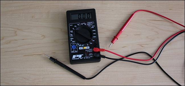
For starters, lets go over some of the different parts of a multimeter. At the very basic level you have the device itself, along with two probes, which are the black and red cables that have plugs on one end and metal tips on the other.
The multimeter itself has a display at the top, which gives you your readout, and there's a big selection knob that you can spin around to select a specific setting. Each setting may also have different number values, which are there to measure different strengths of voltages, resistances, and amps. So if you have your multimeter set to 20 in the DCV section, the multimeter will measure voltages up to 20 volts.

Your multimeter will also have two or three ports for plugging in the probes (pictured above):
- The COM port stands for "Common", and the black probe will always plug into this port.
- The VΩmA port (sometimes denoted as mAVΩ) is simply an acronym for voltage, resistance, and current (in milliamps). This is where the red probe will plug into if you're measuring voltage, resistance, continuity, and current less than 200mA.
- The 10ADC port (sometimes denoted as just 10A) is used whenever you're measuring current that's more than 200mA. If you're not sure of the current draw, start with this port. On the other hand, you would not use this port at all if you're measuring anything other than current.
Warning: Make sure that if you're measuring anything with a current higher than 200mA, you plug the red probe into the 10A port, rather than the 200mA port. Otherwise you could blow the fuse that's inside of the multimeter. Furthermore, measuring anything over 10 amps could blow a fuse or destroy the multimeter as well.
Your multimeter might have completely separate ports for measuring amps, while the other port is specifically just for voltage, resistance, and continuity, but most cheaper multimeters will share ports.
Anyway, let's get started actually using a multimeter. We'll be measuring the voltage of a AA battery, the current draw of a wall clock, and the continuity of a simple wire as some examples to get you started and familiar with using a multimeter.
Testing Voltage
Start by turning on your multimeter, plugging the probes into their respective ports and then setting the selection knob to the highest number value in the DCV section, which in my case is 500 volts. If you don't know at least the voltage range of the thing you're measuring, it's always a good idea to start with the highest value first and then work your way down until you get an accurate reading. You'll see what we mean.

In this case, we know the AA battery has a very low voltage, but we'll start at 200 volts just for the sake of example. Next, place the black probe on the negative end of the battery and the red probe on the positive end. Take a look at the reading on the screen. Since we have the multimeter set to a high 200 volts, it shows "1.6" on the screen, meaning 1.6 volts.

However, I want a more accurate reading, so I'll move the selection knob lower down to 20 volts. Here, you can see that we have a more accurate reading that hovers between 1.60 and 1.61 volts. Good enough for me.

If you were to ever set the selection knob to a number value lower than the voltage of the thing you're testing, the multimeter would just read "1", signifying that it's overloaded. So if I were to set the knob to 200 millivolts (0.2 volts), the 1.6 volts of the AA battery is too much for the multimeter to handle at that setting.
In any case, you might be asking why you would need to test the voltage of something in the first place. Well, in this case with the AA battery, we're checking to see if it has any juice left. At 1.6 volts, that's a fully-loaded battery. However, if it were to read 1.2 volts, it's close to being unusable.
In a more practical situation, you could do this type of measuring on a car battery to see if it might be dying or if the alternator (which is what charges the battery) is going bad. A reading between 12.4-12.7 volts means that the battery is in good shape. Anything lower and that's evidence of a dying battery. Furthermore, start your car up and rev it up a bit. If the voltage doesn't increase to around 14 volts or so, then it's likely that the alternator is having issues.
Testing Current (Amps)
Testing the current draw of something is a bit trickier, as the multimeter needs to be connected in series. This means that the circuit you're testing needs to be broken first, and then your multimeter is placed in between that break to connect the circuit back up. Basically, you have to interrupt the flow of current in a way---you can't just stick the probes onto the circuit wherever.

Above is a crude mockup of what this would look like with a basic clock running off of a AA battery. On the positive side, the wire going from the battery to the clock is broken up. We simply place our two probes in between that break to complete the circuit again (with the red probe connected to the power source), only this time our multimeter will read out the amps that the clock is pulling, which in this case is around 0.08 mA.
While most multimeters can also measure alternating current (AC), it's not really a good idea (especially if its live power), since AC can be dangerous if you end up making a mistake. If you need to see whether or not an outlet is working, use a non-contact tester instead.
Testing Continuity
Now, let's test the continuity of a circuit. In our case, we'll be simplifying things quite a bit and will just use a copper wire, but you can pretend that there's a complex circuit in between the two ends, or that the wire is an audio cable and you want to make sure it's working fine.
Set your multimeter to the continuity setting using the selection knob.

The readout on the screen will instantly read "1", which means that there isn't any continuity. This would be correct since we haven't connected the probes to anything yet.

Next, make sure the circuit is unplugged and has no power. Then connect one probe to one end of the wire and the other probe to the other end---it doesn't matter which probe goes on which end. If there is a complete circuit, your multimeter will either beep, show a "0", or something other than a "1". If it still shows a "1", then there's a problem and your circuit isn't complete.

You can also test that the continuity feature works on your multimeter by touching both probes to each other. This completes the circuit and your multimeter should let you know that.
Those are some of the basics, but be sure to read over your multimeter's manual for any specifics. This guide is meant to be a starting point to get you up and running, and it's very possible that some things shown above are different on your particular model.