Quick Links
In pretty much every house where an outlet is close to a water source, you’ll usually find what's called a ground fault circuit interrupter (GFCI). This is a type of outlet that's meant to quickly shut off power at that outlet when it detects a short circuit or a ground fault.
Warning: This is a project for a confident DIYer. There’s no shame in getting someone else to do the actual wiring for you if you lack the skill or knowledge to do so. If you read the beginning of this article and immediately visualized how to do it based on past experience wiring switches and outlets, you’re probably good. If you opened the article not sure how exactly we were going to pull this trick off, it’s time to call in that wiring-savvy friend or electrician. Also note that it may be against the law, code, or regulations to do this without a permit, or it might void your insurance or warranty. Check your local regulations before continuing.
What Are GFCI Outlets and How Do They Work?
Normal electrical flow happens when the current comes through the hot wire, provides power to whatever is plugged in, and returns back through the neutral wire. But if electricity flows beyond that, the GFCI outlet will trip (a.k.a. instantly turn off).
In other words, if you happen to be using a faulty hair dryer and your feet are wet, a short circuit from the faulty hair dryer can cause the current to pass through you and into the ground, electrocuting you. However, a GFCI outlet will kill the power before the current can even remotely escape the hair dryer, usually within 30 milliseconds or so.

Electrical code requires that GFCI outlets be installed in locations like the kitchen, bathroom, and outdoors where water has the risk of splashing onto electronics, but sometimes (especially in older dwellings), GFCI outlets are nowhere to be found. In fact, GFCI outlets weren't widely common in households until the early 1980s.
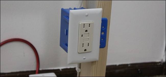
If you look around your house and don't see GFCI outlets where there should be, then it's time to replace those outlets with proper GFCI receptacles. You can easily spot a GFCI outlet if it has two small buttons between the two receptacles that say "Reset" and "Test". A normal outlet won't have these buttons.
You could install a GFCI circuit breaker on your circuit breaker box (all houses built after 2014 should already have these), which will protect that entire circuit from ground faults without needing to install GFCI outlets, but they’re much more expensive compared to a few GFCI outlets, especially if you need to replace several breakers. Plus, if you install a single GFCI outlet at the beginning of a circuit, all outlets following in that circuit will be protected anyway.
So essentially, a small handful of GFCI outlets can protect your entire house. But you really only need to install GFCI outlets where there's a water source of some kind, whether it's in the kitchen, bathroom, outside, or in the garage. Here's how to replace a traditional outlet with a GFCI outlet.
What You'll Need

Before you dive deep into replacing your outlets, you'll need a few tools to do the job.
The absolute must-have tools include a flat-head screwdriver, a Phillips-head screwdriver, and a voltage tester. The voltage tester is to determine which wires are the "load" wires and which wires are the "line" wires, because you'll need to connect them to the proper terminals on the GFCI outlet (more on that further down).
Some optional–but very handy–tools include some combination pliers (for twisting wire together if needed), a wire stripper tool (in case you need to cut wire or strip off wire housings), and needle-nose pliers to bend wire to your will.
You also need the GFCI outlet. You don't need to get super fancy here, and any GFCI outlet will do the trick--just make sure UL-certified by looking for this logo on the outlet when you go to buy one. This one from Leviton is a great option.
Step One: Turn Off the Power at the Breaker Box

Before you actually start taking things apart, you need to shut off the power to the outlet by turning off the appropriate breaker at the breaker box.
Most of the time, you'll only need to turn off one breaker, but sometimes houses have unique wiring setups where some outlets are connected to two breakers (like my house). This actually isn't too rare, as outlet junction boxes sometimes serve as junction boxes for other circuits passing through.
Your circuit breaker should have a diagram of which breakers control which areas of your house, but to be sure that you turned off the correct breaker, a good trick is to plug in a stereo and crank the music so that you can hear it from the breaker box. Once the music stops, then you hit the right breaker. Again, there may be a second breaker you'll need to flip, so it's a good idea to test the wiring inside the outlet box before you start messing with it, as described below.
Step Two: Remove the Existing Outlet
Start by taking your flat-head screwdriver and removing the small screw in between the two receptacles.

From there, you can remove the faceplate.

Next, before you begin removing the actual outlet, take your voltage tester and stick it into the junction box to see if any of the wires are still live. If so, then you'll need to shut off another breaker in order to kill power completely to that outlet.

Next, take your Phillips-head screwdriver and remove the two screws that hold the outlet onto the junction box.

Once removed, take your fingers and pull the outlet out of the junction box using the tabs at the top and bottom of the switch to expose more of the wires.

Take a look at how the outlet is wired up. You’ll notice that there are two black wires connected to the outlet on one side, and two white wires on the other side, as well as a bare copper wire connected to a green screw. The black wires are the power (or “hot”) wires, the white wires are the neutral (or “return”) wires, and the bare copper wire is the ground wire. Electricity flows through the hot wire, entering the outlet and then into whatever is plugged into it, and then returns through the neutral wire (these wires are known as the "line" wires). However, the extra black and white wires are for continuing the circuit to other areas of the house, so the outlet is also acting as a junction of sorts. These are known as the "load" wires.
Take your Phillips-head screwdriver and unscrew the terminal screws for all of the wires--including the ground wire--and remove them from the outlet.

You can then put the old outlet off to the side and you'll be left with five wires: two black wires, two white wires, and one ground wire. If the outlet you're replacing is at the end of the circuit, it wouldn't have the extra pair of black and white wires, since it doesn't need to continue the circuit, so you'll only have one black wire, one white wire, and one ground wire in that case.

Step Three: Determine the "Line" and "Load" Circuits
Normally, when connecting a regular outlet to these wires, you can put either black wire on whichever brass screw, and the same goes for the white wires on the silver screws. However, when connecting a GFCI outlet, you have to connect a specific black wire to a specific screw on the outlet. If you look on the back of your GFCI outlet, you'll notice that there are two screws for "Line" and two screws for "Load".

This means that one pair of black and white wires are the line wires, and other pair is the load, but how do you determine which is which? Sometimes you'll get lucky and the original outlet will have the line and load terminals already marked (sometimes with an "L" for line and "T" for load). It's also common practice for electricians to wire the load wires on top and the line wires on the bottom, just like on GFCI outlets. However, don't trust that completely, as it's not a standard code procedure by any means.
Either way, it's a good idea to determine which wires are line and load so that you're absolutely sure. To do this, we'll be using the handy-dandy voltage tester that we used earlier.
The first step is to screw a wire nut onto each wire (except for the ground wire, as it doesn't need one) and spread out the wires as far apart as possible. You might need to use your needle-nose pliers to straighten out the wires first so that you can stick wire nuts onto them.

Once that's done, turn the power back on to the outlet and carefully place the voltage tester near each wire. When the voltage tester lights up or makes a noise next to a wire (it will be one of the black wires), mark that wire in some way. I usually make a quick mark on the wire nut with a permanent marker. This is one of the line wires.

Next, turn the power back off and then go back to your junction box. To determine which of the white wires pairs with the black wire that you just marked, simply follow the marked black wire back to where it enters into the junction box. You'll notice that it's paired with a white wire. That white wire is the other line wire, and by doing this you've also determined which black and white wires are the load wires.

Step Four: Install the GFCI Outlet
Remove the wire nuts from all the wires, and begin by connecting the black line wire to the brass screw of the "Line" side of the GFCI outlet. You can do this by curling the wire around the screw itself and tightening it, or leaving it straight and sticking it into the small hole on the back of the outlet and then tightening the screw down. The latter method is easier, but it's not quite as solid of a connection as the former. Still, it should hold up just fine.

Do this for the white line wire on the opposite side where the silver screw is. Continue this for the load wires, using the same procedure as all of the other wires.

Also, don't forget to connect the ground wire to the green screw on the outlet!

Next, you’ll need to stuff the wires and outlet back into the junction box. GFCI outlets are a bit bigger than regular outlets, so this can be tricky, but don’t be afraid to get rough with the wires and bend them back into the box as far as they’ll go, as well as pushing the outlet into the junction box with a bit of force.

With that GCI outlet in place, use the two included screws to affix the outlet to the junction box.

Next, mount the faceplate over the outlet and secure it with the two small screws.

Turn the power back on and the first thing you'll notice with the GFCI outlet is that it will begin in a tripped state and the small light on the outlet lights up whenever it's tripped. Simply press in the "Reset" button to bring power back to the outlet.
Technically, if you want to protect all the outlets on a circuit, you only need to replace the first outlet in that circuit with a GFCI outlet. However, if an outlet further down the circuit gets tripped, all of the previous outlets in that circuit will trip as well, forcing you to find the GFCI outlet that's first in the circuit and reset it.
With that said, there's no harm in replacing every single outlet with a GFCI outlet, so when that outlet trips, only that one outlet will go down without affecting any of the other outlets. But it's certainly more cost effective to only replace a few outlets in your house, since GFCI outlets are a bit more expensive than traditional receptacles.